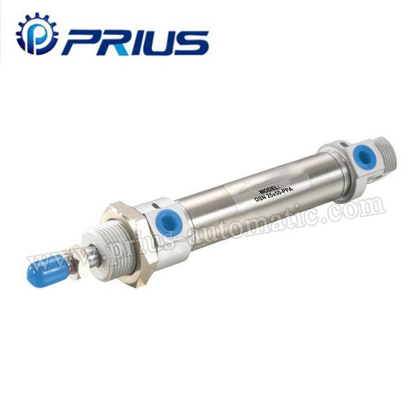
DSN Edelstahl Mini-Zylinder

Bestellcode
Spezifikation
| Bohrung (mm) | 12 | 16 | 20 | 25 | 32 | 40 | |
| Bewegungsmuster | Doppeltwirkend oder einfachwirkend | ||||||
| Arbeitsmedium | Luft | ||||||
| fester Typ | Normaler Typ LBType FAType FBTYPE SDBType | ||||||
| Arbeitsdruckbereich | 1 ~ 9,0 Kgf / cm 2 | ||||||
| Gesicherte Druckbeständigkeit | 13,5 Kgf / cm2 | ||||||
| Betriebstemperaturbereich | 0 ~ 70 ℃ | ||||||
| Betriebsdrehzahlbereich | 50 ~ 800 mm / s | ||||||
| Puffer Typ | Dichtung Buffer | Verstellbare Puffer | |||||
| Anschlussgröße | M5x0.8 | G1 / 8 " | |||||
Interne Struktur
 |
NEIN. | Bezeichnung | NEIN. | Bezeichnung |
| 1 | Kolbenstange | 9 | Stainless Steel Tube | |
| 2 | Kolbenstangenmutter | 10 | Kolbenstange O-Ring | |
| 3 | Front Cover Siegelring | 11 | Pistion O-Ring | |
| 4 | Lager | 12 | Magnet (Optional) | |
| 5 | Inbusschraube | 13 | Ring tragen | |
| 6 | Vorderseite | 14 | Kolben | |
| 7 | Buffer Ring | 15 | Inbusschraube | |
| 8 | Rohrwand O-Ring | 16 | Zurück Over |
Schlaganfall
| Bohrung (mm) | Standard Stroke | Max.Stroke | zulässige Stroke | |||||||||||||||
| 12 | 25 | 50 | 75 | 80 | 100 | 125 | 150 | 160 | 175 | 200 | 300 | 500 | ||||||
| 16 | 25 | 50 | 75 | 80 | 100 | 125 | 150 | 160 | 175 | 200 | 300 | 500 | ||||||
| 20 | 25 | 50 | 75 | 80 | 100 | 125 | 150 | 160 | 175 | 200 | 250 | 300 | 500 | 650 | ||||
| 25 | 25 | 50 | 75 | 80 | 100 | 125 | 150 | 160 | 175 | 200 | 250 | 300 | 350 | 400 | 450 | 500 | 500 | 650 |
| 32 | 25 | 50 | 75 | 80 | 100 | 125 | 150 | 160 | 175 | 200 | 250 | 300 | 350 | 400 | 450 | 500 | 500 | 650 |
| 40 | 25 | 50 | 75 | 80 | 100 | 125 | 150 | 160 | 175 | 200 | 250 | 300 | 350 | 400 | 450 | 500 | 500 | 650 |
Gesamtabmessungen
| Bohrloch | EIN | A1 | A2 | AM | SEIN | BF | CD | D | EE | EX | EW | G | KK |
| 12 | 103 | 103 | 87 | 16 | M16 x1,5 | 16 | 6 | 21 | M5 | 19 | 12 | 10 | M6 x1.0 |
| 16 | 112 | 112 | 96 | 16 | M16 x1,5 | 16 | 6 | 21 | M5 | 19 | 12 | 10 | M6 x1.0 |
| 20 | 125 | 121 | 105 | 20 | M22 x1,5 | 18 | 8 | 30 | G1 / 8 | 27 | 16 | 15 | M8 x1.25 |
| 25 | 136 | 134 | 116 | 22 | M22 x1,5 | 20 | 8 | 30 | G1 / 8 | 27 | 16 | 16 | M10 x1.25 |
| 32 | 150 | 143 | 125 | 23 | M27 x2.0 | 20 | 10 | 38 | G1 / 8 | 35 | 20 | 16 | M10 x1.25 |
| 40 | 150 | 143 | 125 | 23 | M33 x2.0 | 20 | 10 | 45 | G1 / 8 | 42 | 20 | 16 | M14 x1,5 |
| Bohrloch | KU | V | L | L1 | MM | NI | NJ | WF | Z1 | X | J | AR | ich | AXT | AY |
| 12 | 5 | - | 4 | 16 | 6 | - | - | 22 | 49 | - | 5 | 6 | 10 | 24 | 27.5 |
| 16 | 5 | - | 9 | 16 | 6 | - | - | 22 | 58 | - | 5 | 6 | 10 | 24 | 27.5 |
| 20 | 7 | 22 | 12 | 22 | 8 | 15 | 28.5 | 24 | 59 | 2 | 6 | 7 | 12 | 33 | 29 |
| 25 | 9 | 22 | 12 | 22 | 10 | 15 | 28.5 | 28 | 64 | 2 | 6 | 7 | 17 | 33 | 29 |
| 32 | 10 | 27 | 15 | 27 | 12 | 19 | 36.5 | 28 | 72 | 2 | 6 | 12 | 17 | 41 | 36 |
| 40 | 14 | 33 | 15 | 27 | 16 | 22.5 | 43,5 | 28 | 72 | 2 | 8 | 11.5 | 22 | 51 | 45 |